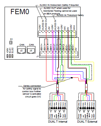
Wiring Diagrams for Optex Sensors
Principle of operation using a single port for communication.
When the test signal is initiated from the control board over Red/Blue it sends out a 10ms pulse, this triggers the safety sensor output (Grey/Pink) to change to active state (high to low) for the same 10ms pulse duration.
If the control box does not see this signal within a set time of sending out the test signal it responds in a safe manner. Working on this principle - if you change the test input from low to high for any duration the corresponding safety circuit will also change from high to low for the same duration.
You can test all the sensors in a series circuit one after the other for monitoring and also enable them to operate the door controller for normal safe operation.
You can test all the sensors in a series circuit one after the other for monitoring and also enable them to operate the door controller for normal safe operation.
The Control Board sends a test signal to the Inside sensor, the IR curtain output will, in turn, send a signal to the test circuit of the outside sensor which will, in turn, send a signal to the control box satisfying the monitoring from the control box.
If the inside sensor operates it sends a signal to the test input on the outside sensor which in turn operates the safety output signal, this is fed back to the control board and the door responds by not closing as the IR curtain is active.
If the outside side IR curtain is activated, then the sensor will, in turn, send a signal to the control box which responds by not closing as the IR curtain is active.
Wiring in this format ensures that any test failure on all sensors is certain to be captured.


